Education FCCP: Fuel Cell E-cargo pedelecs technology
This page will focus on the energy technology of the FCCP:
- FCCP Energy System and its Objective
- Fuel Cell Stacks for FCCP
- Fuel Cell System with Pre-Heater
- Hydrogen System (on Bord Storage and Refuelling)
- Data Acquisition
- Fuel Cell Cargo Pedelecs
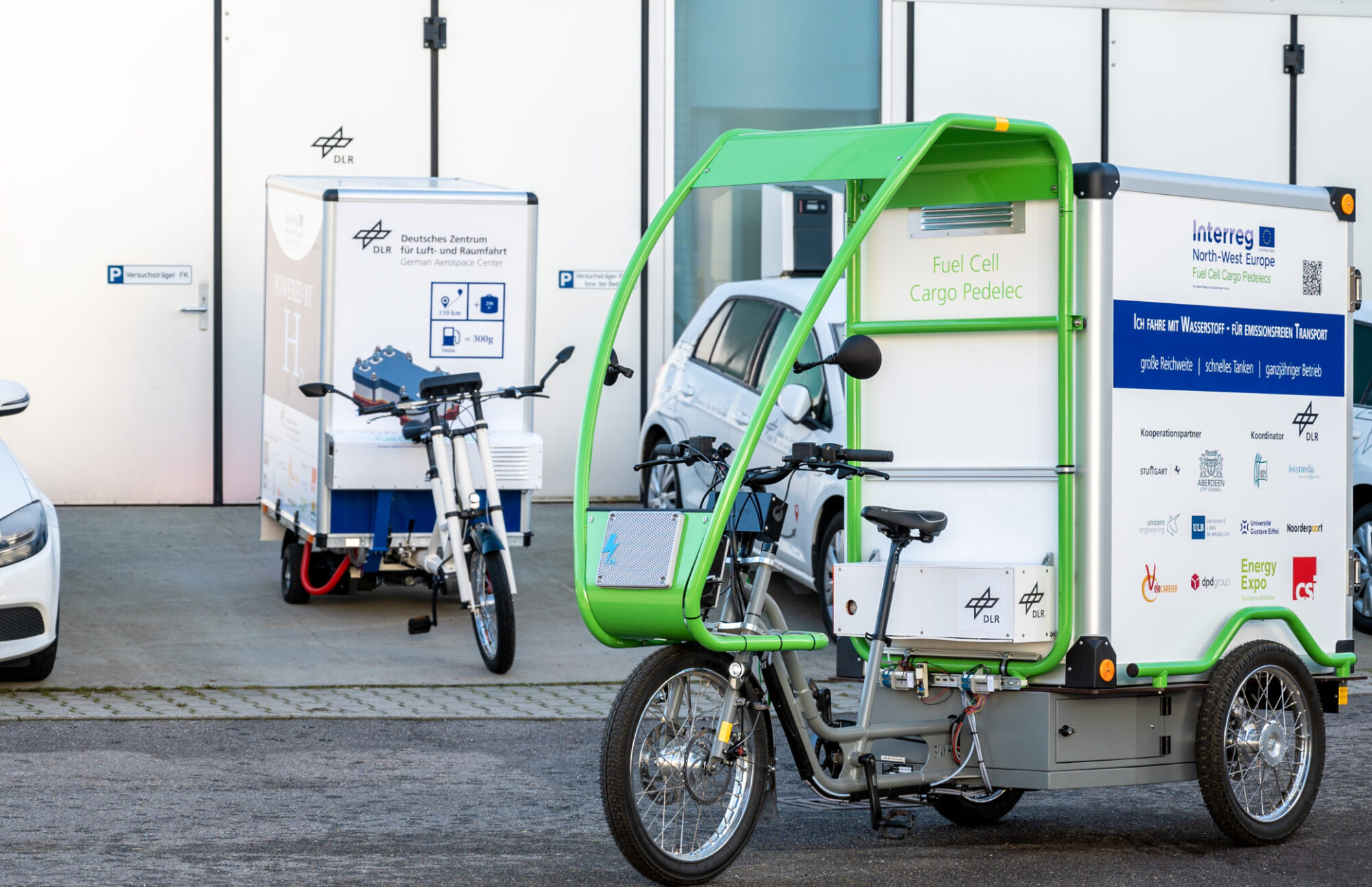
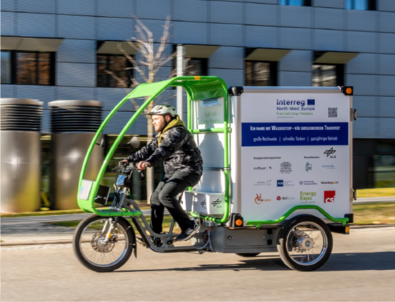
Figure below shows the FCCP running in front of the German aerospace centre.
The objective for integrating fuels are into cargo bikes was 1. development and adaptation of fuel cell system; 2. development and integration of a hydrogen storage and fuel cell system adapted to the FCCP; 3. Technical verification of the FCCP; 4. Build-up of fuel cell cargo pedelecs; 5.Validation of technology in daily operation.
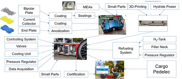
The figure above shows the parts of the FCCP Energy System which is much more than putting a hydrogen tank and fuel cells on the cargo bike as a range extender. The German aerospace centres has built up the fuel cell. The upper left part shows the fuel cell components. The centre part shows the fuel cell system as a whole. On the right side the hydrogen refilling system hydrogen storage are shows and finally the bottom shows the cargo bike.
Of course certifications are needed and sometimes the insurance depending on the place where you are using the cargo bike.
The fuel cell system requirement was a power output of about 400 Watt and the operation range between minus 22 to up to 40 degrees Celsius. In North West Europe we need to be able to cope with the cold weather. The system is connected to the cargo battery as a range extender: so a fuel cell equipped cargo pedelec has a much larger driving range than a normal battery cargo pedelec.
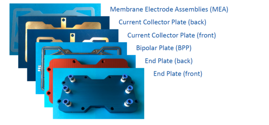
The figure above shows the components of the fuel cell. For the final stack 22 cells will be pressed together.
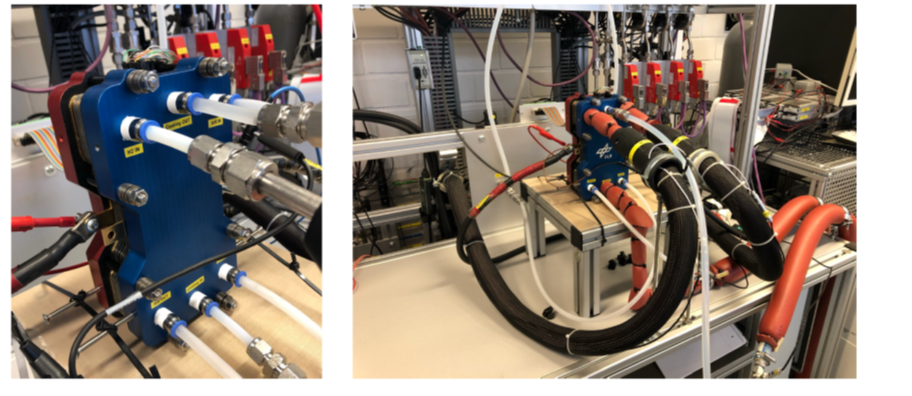
The figure above shows the fuel cell stack on the test bench in a German aerospace centre.
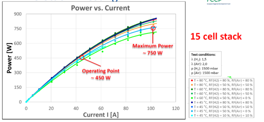
The figure above shows the power versus current curve for a 15 cell stack. At about 45 degrees Celsius operation temperature it delivers about 750 Watt. The cargo bike will be operated at about 450 Watt with 50 Watt for the balance of plant. So there is a lot reserve in case more power is needed.
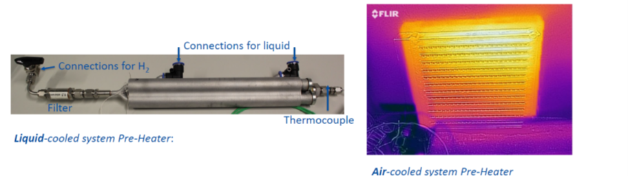
The figure above shows the Pre-heater which is integrated in the cooling system of the fuel cell. This cooling system is needed because the fuel cell system makes electricity and heat. Additionally a minimum temperature is needed to operate the fuel cell. To get to this operation temperature of about 45 to about 60 degrees Celsius the pre-heater enables for faster start up in very cold conditions. In the project two different models of fuel cells are used: the liquid cooled fuel cell and the air cooled fuel cell. For both system a pre heater has been made. The pre-heater uses the pressure difference of the tank to create heat via a metal hydride intermediate storage. The metal hydride gets warm and you can use this to heat to warm up water. The figure shows on the left side is the liquid pre-heater and on the right side the pre-heater for the air flow through the fuel cell. A large advantage of this process is that no extra energy for a quicker start at frozen conditions is needed.
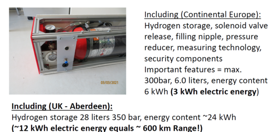
The hydrogen system storage system, shown in the figure above, is basically a carbon fibre wrap type 4 cylinder with plastic inner liner. It is 6 litre cylinder at 300 bars with an energy content of 6 kWh (3 kWh electric energy at 50% efficiency of the fuel cell). Because of the availability of fuelling station, for the cargo bike in Aberdeen a larger tank is used: 28 litre at 350 bar; 24 kWh of chemical energy and 12 kWh of electrical energy. This corresponds with 600 km range which is sufficient for the whole week driving.
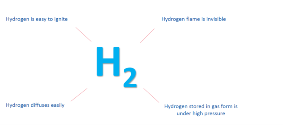
Hydrogen properties are shows in tje figure above: It is easy ignitable and has an invisible flame. It can pass through many materials but if you have a leakage it diffuses in the airway easily to go below explosive limit. In most applications hydrogen is stored under compressed conditions. Liquid hydrogen is possible but its technology for rockets and so it is not the technology for the small volume cycle cargo bikes.
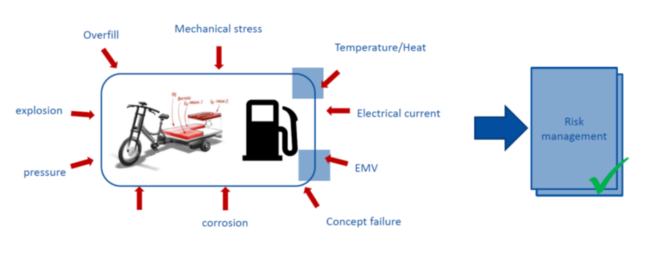
Hydrogen safety is an issue. As any fuel contains energy because that’s the reason for using a fuel. And every fuel contains energy can release this energy vastly. So petrol is also dangerous good as is hydrogen and are high voltage batteries. So always you have to take care. The risk assessment considers different environmental conditions like mechanical stress, explosion, pressure, corrosion failures, temperature heat, electric current and electromagnetic waves which make an computer failures on the system. See Figure above.
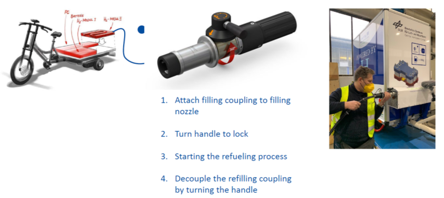
The hydrogen refuelling, see figure above, is a pretty easy processes comparable to filling of a natural gas powered car: first attach the filling nozzle and turn the handle to lock and start filling process. After filling station signals for full or after there is no filling noise anymore the refilling system can be decoupled.
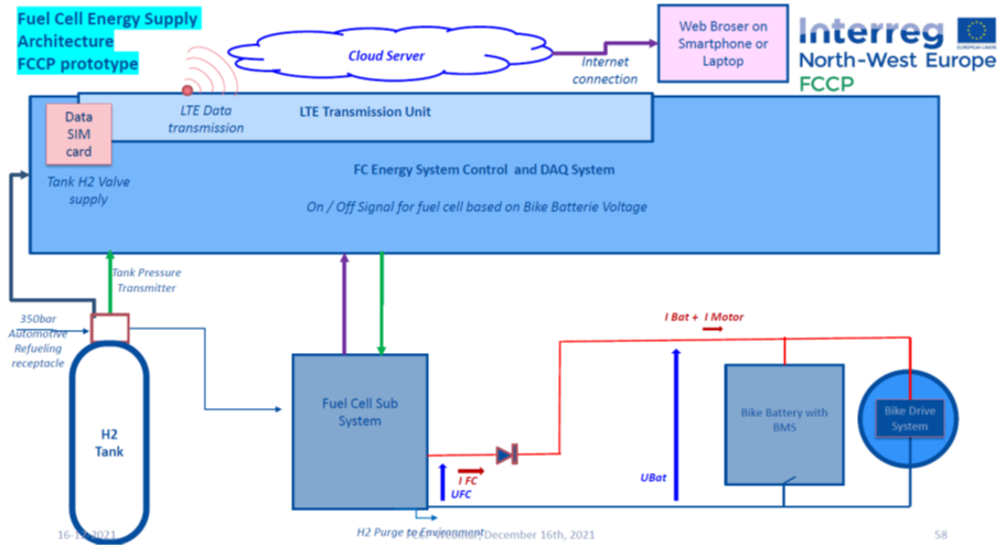
The figure above shows a simplified overview of the data acquisition system which is connected to the hydrogen tank , the fuel cell subsystem, the battery and the electrical motor. Based on the collected data the system controls the opening close of the hydrogen valves on the tank. By measuring the fuel cell and battery voltage and the fuel cell current and battery current it starts the fuel cell if the battery is low in voltage. The fuel cell keeps recharging the battery throughout 90% state of charge. The buffer capacity to 100% state of charge is needed for the cooperative breaking. All data will be stored on SD card on the bike with a high resolution and with a lower resolution the data are send to a cloud server every second.
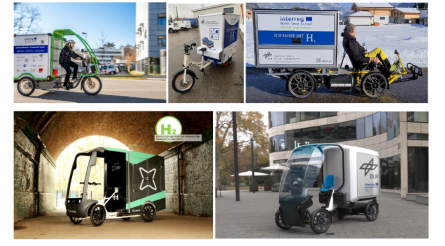
The figure below shows a few of cargo pedelecs currently equipped with a fuel cell.
fig 4.23
Restricted area (FCCP project members; For the links: please login on the FCCP teams site)
The theoretical base consists of:
- FCCP Technology presentation: link
- WP T2 Deliverable 6.1 Knowledge about the certification process for the integration of fuel cells into cargo pedelecs
- WP T2 Deliverable 7.1 Knowledge for selection of the energy system
- Technical documentation Cargo Pedelecs
- Technical documentation filling station (including safety): link